
Entity-Relationship Diagram (ERD) is the tools used to perform the modeling of data. In the development of an information system, the needs of the data need to be handle by the system can be documented through ERD. ERD document the data entities that need to be recorded, processed, stored, and distributed through the information system will be built. Data entities are the things needed by the system for stored information.
 |
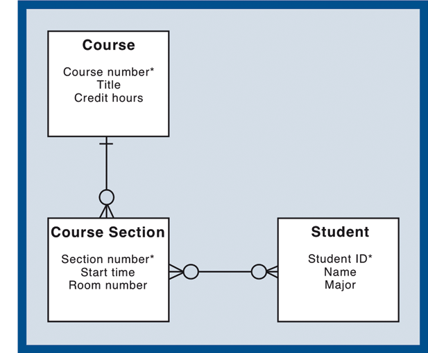
| figure 1 |
Figure 1 is a simple example of an ERD. ERD can be described with attributes or attributes (Figure 1 and 2). Further, it should be noted that the relationship and cardinality (keep in mind that the ERD is not part of UML) that occur in between things must be read both ways (binominal direction). For example, in Figure 2 are:
- From the side of the customer – order, a customer may not order or order a lot of order.
- From the side of order – customer, one order (one even read from fixed minimum is zero) can be requested by only one customer.
If there is a relationship many-to-many between entities (Figure 2), then the relationship need to be refined. Refining the relationship is done by creating a new entity among relationship many-to-many of these (Figure 3). The new entity should be able to represent events that connect the two types of these entities. Further, the entity can also be translated into a table. Refined entity that exists in an ERD is also reflected in a relationship many-to-many between tables through normalization.
 |
| figure 2 |
 |
| figure 3 |

1 comments :
Click here for commentsHelpful post!!
active collagen reviews
active collagen supplements
Buy Lorna Vanderhaeghe
buy vega online
Buy Lorna Vanderhaeghe Estrosmart
Buy Lorna Vanderhaeghe Supplements
Lorna Vanderhaeghe Active Collagen
lorna vanderhaeghe estrosmart
lorna vanderhaeghe health products
lorna vanderhaeghe products
lorna vanderhaeghe thyrosmart
lorna vanderhaeghe website
estrosmart
cheap vitamins online canada
Conversion Conversion Emoticon Emoticon